Sankey Diagram Page
Purpose: A Sankey Diagram Page helps operators visualize and
understand flow distributions, where the width of connecting links represents
the proportional quantity of material, energy, or resources flowing between
nodes. This makes it ideal for analyzing efficiency, identifying bottlenecks,
and tracking resource allocation throughout processes.
Characteristics
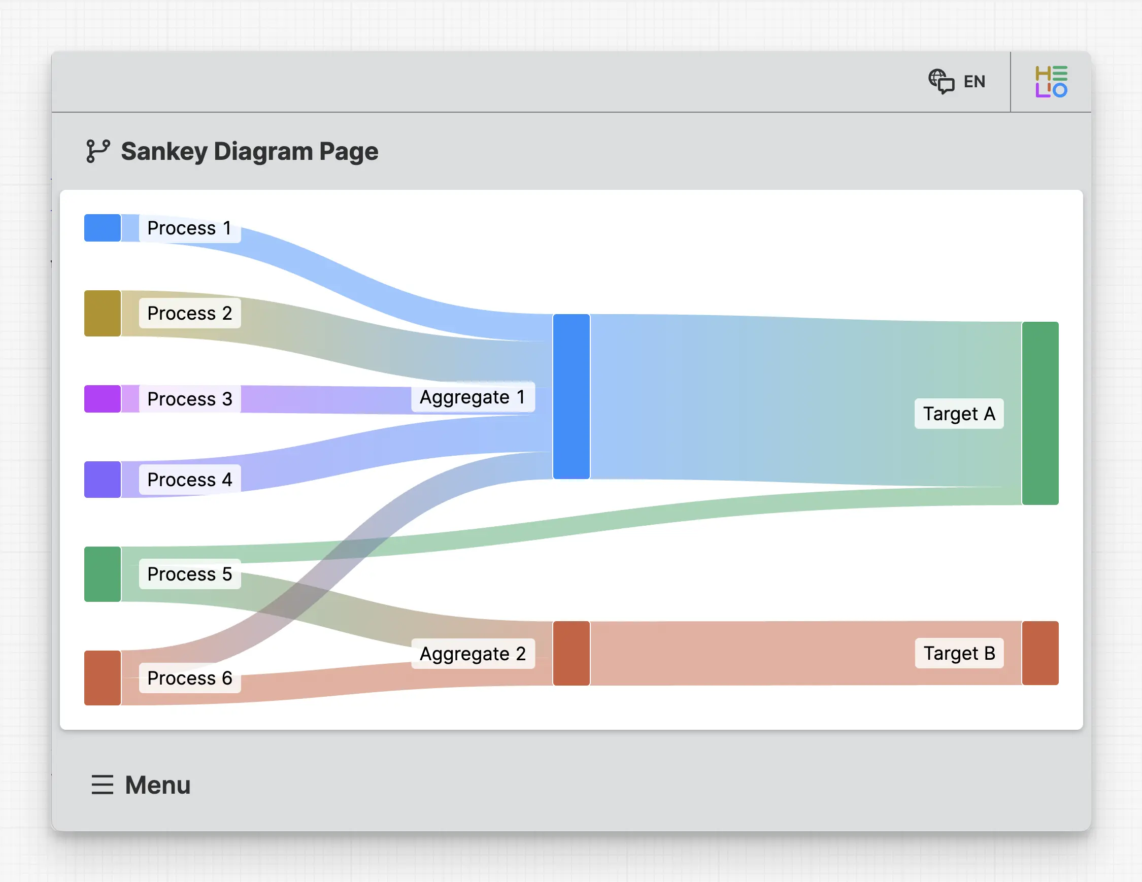
A Sankey Diagram Page displays flows between multiple nodes where link
width indicates the quantity or magnitude of the flow. The diagram
automatically scales link widths proportionally, ensuring that flow
relationships are accurately represented and easy to compare at a glance.
Anatomy

Title and Icon
Sankey Node
Sankey Node Link
Adding & Linking Nodes
Each Sankey Node represents a point in your flow diagram. To add a node:
- Select the
Sankey Diagram Pagein the HMI Content Tree - Add a new
Sankey Nodeelement - Configure its properties in the properties panel
The Sankey Diagram automatically calculates proportions based on the values you define:
- Link widths are drawn proportionally to represent the relative quantity of each flow
- Multiple outgoing links from a single node will split the flow visually
- The sum of outgoing link values equals the total input to that node
Properties
General
Title
Page reference
This optional property lets you define unique short code that is human readable and helps to refer to that page without specifying its actual name. This is helpful especially in multilingual environments because
- It helps your Support-Team to quickly navigate users.
- It can be picked up by the product manual and documentation.

Icon
This icon will be displayed in the main navigation, the page header, and inside an embedded navigation of a Page Group.
Navigation
Show/Hide Page
Page Section Conditions
Page header
Display Condition
true or false you're good to go.Display Labels
Condition
Specify whether the node labels should be visible. Hiding labels can be helpful on smaller devices.